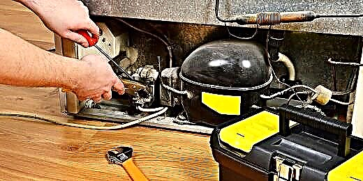
In case of any breakdown, most owners of the gas column call the master of a specialized service. However, services are usually accompanied by financial costs, right?
Why not independently solve a seemingly insignificant problem, having the skills of a mechanic? With a situation when the gas valve on the gas column does not work, you can try to cope on your own. But what is needed for this and where to start?
In this article we will talk about the design features of the gas valve. We will analyze the main breakdowns that lead to the inoperability of the column. For a better understanding of the process of diagnosis and disassembly, we will provide the presented material with visual photographs and a video.
Geyser valve device
In order to facilitate the process of restoring the gas boiler to working capacity, in particular, when a gas valve malfunction is noted, we will consider the assembly of the unit and the technical nuances of diagnosis and repair.
But, if you do not have experience in disassembling geysers and relevant knowledge on the topic, it is preferable to invite a master for repair and maintenance.
The device, called the gas solenoid valve, performs an important function of the gas column - control the flow of the fuel component (natural gas). The picture below shows a common version of the design of the control unit, which includes the valve.

Appearance of the unit that performs the function of adjusting the gas supply to the gas burner system of the boiler (column). The device includes an electromagnetic gas valve (1), a manual rod (2)
In fact, the control unit is a two-stage mechanism, the first stage of which is precisely the gas solenoid valve (1). The second stage is a mechanical device that provides adjustment by means of a manual control rod (2).
The design of the gas valve is quite simple - it is made according to the principle of an electromagnetic traction device, which are used as part of a wide variety of devices and devices. If you dismantle this component from the circuit of the control unit, for which it is enough to unscrew a couple of screws, the valve part will appear before the eyes of the master, which is mounted on a spring-loaded metal rod.

This is what the inside of the device looks like (in fact, the valve itself), after dismantling the gas valve from the control unit of the column (boiler)
As you can see in the picture, the design consists of skirtswhere the valve part enters - membrane and electromagnetic module. The valve part is mounted on a metal stockspring-loaded for the return stroke to the closed position.
When voltage is applied to the coil of the electromagnet, the metal rod moves upward under magnetic action and diverts the membrane from the passage opening of the skirt. This opens the gas passage towards the manual valve and further to the burner.
Valve troubleshooting
The loss of efficiency of the gas valve leads to the complete impossibility of operating the heating equipment, or to a situation where the required heating level is not provided due to incomplete opening of the membrane.
On the other hand, there are possible causes, on the contrary, leading to a constant flow of gas to the burner of the boiler (column). That is, a situation arises when the gas valve is constantly open.
Stage # 1 - Simple Electrical Component Inspection
It is permissible to test the performance of the gas solenoid valve on the column (boiler) without dismantling the control device. However, to perform a test directly on the equipment, it is necessary to ensure that the gas supply is turned off by closing the valve on the line. In this case, the geyser (boiler) remains connected to the electrical network.

Microswitch installed on the gas flow control device. This component of the circuit switches the supply voltage supplied to the basic elements, including the electromagnetic gas valve
As a rule, an electronic component is present on the device for regulating the gas supply to the burner - a micro switch (see the picture above), by which, when the gas column is turned on, power is supplied to the main technological parts.
In particular, the supply voltage through the micro-switch is supplied:
- to the ignition module;
- to the fan of the traction turbine;
- to the coil of the solenoid valve.
So, if it is forced, for example, with a screwdriver blade, to act on the pusher plate of the microswitch, these gas column systems (boilers) will receive power.
As a result, the following components are activated:
- a fan;
- electric lighters;
- solenoid valve.
That is, the tester will hear the sound of a running fan, the characteristic clicking sounds of a gas lighter, and, of course, the characteristic click of the solenoid valve stem. This condition of the equipment demonstrates the health of the components, in any case - electrical.
Stage # 2 - Disassembling and Testing the Valve
The cause of inoperability of the unit may be various defects.
Among them:
- violation of the shape of the membrane seal;
- getting into the skirt body of a foreign object;
- fracture (wedge) of the return spring;
- break in the conductor of an electromagnet coil.
The first three defects of the list are detected after disassembling the device with a careful inspection of the structure and checking the rod for free axial movement.

The loose fit of the membrane seal to the skirt plate and the ease of stem travel are the primary testing steps after disassembling the mechanism
A separate approach to testing requires the last item on the list - coil conductor break electromagnet. We will discuss further the types of breakdowns and methods for their elimination.
Stage # 3 - check the electromagnet coil and its repair
The practice of operating gas columns and boilers shows that a defect in an electromagnet coil is not only a break in the winding conductor.
Cases are common interturn circuit, which also leads to a loss of operability of the node. How to check the solenoid valve of a household gas column at home?

Testing any inductor with a tester is a common practice for repair. Accordingly, the coil of the gas solenoid valve is also checked for open or inter-turn short circuit using this device
Of course, each individual manufacturer of gas water heaters (boilers) uses original valve designs. Therefore, the resistance of the inductance coils that make up the electromagnet are significantly different.
In general, one can note a certain range of resistances characteristic of such inductances: 1.3 - 7.5 kOhm. In fact, a specific parameter should indicated in the documentation for the equipment.
Inductor measurement is traditionally carried out in the resistance measurement mode - by connecting the tester probes to the contacts of the inductor.If the device does not respond to the connection, it is obvious that there is an open circuit.
If the measured resistance parameter differs from that indicated in the documentation, most likely there is an interturn circuit. In both cases, the coil should be replaced.

The picture shows the resistance of the working (serviceable) coils of the gas valves of Baxi boilers, in particular, the devices of the SIT SIGMA 845078 series
In practice, replacing a coil as a separate valve element of a gas boiler is rare. As a rule, if it is a failure of the inductance coil that is detected, the craftsmen completely change the solenoid valve assembly.
This replacement is due to the complexity of the search for a specific component. And the procedure for replacing an individual element is more complicated than replacing a gas solenoid valve assembly.
Stage # 4 - troubleshooting mechanical defects
As noted above, a solenoid valve for a domestic gas water heater may lose functionality for purely mechanical reasons. For example, the accidental appearance of a foreign element inside the valve threatens with a loss of tightness of the membrane seal.
To find the cause of the breakdown, the wizard has to perform a series of actions:
- we remove the gas valve;
- its subsequent disassembly;
- attentive check.
These manipulations can detect and eliminate the malfunction associated with the ingress of foreign objects into the working chamber.

Visual inspection of the surfaces of the landing plate of the valve skirt reveals the reasons for insufficient sealing of the seal in the gas flow closure mode on the column
Among mechanical defects, a fairly common moment is elastic membrane defectwhen there is a violation of the form or partial destruction of the landing site. Here, in principle, you can get by installing a new membrane on the stem, but traditionally masters in such cases resort to a complete replacement of the electromagnetic valve.
A similar situation with device repair when it comes to return spring or loss of necessary pressure by this element. To replace the spring, you have to disassemble the entire structure.
However, some valve models are assembled using a screwless joint - rivet method or metal clips. Therefore, it is much easier to replace the design completely than to engage in restoration.
Stage # 5 - valve assembly and leak test
If the troubleshooting of the gas solenoid valve involved disassembling the mechanical structure, reassembly should include careful leak check. Be sure to check gasket integritymounted on the upper rim of the skirt; if necessary, replace the gasket.

Gasket on the side of the skirt. This element should be paid increased attention to during assembly of the structure, since the gasket is often damaged during disassembly
The assembled unit is checked in a standard (traditional) way with the gas supply turned on. A suitable container is taken, where a little water is poured and soap powder is added. Is being created thick soapy foamwhich is applied to the skirt body in the place where the gasket is installed. If bubble formation is not visually observed, then tightness is within normal limits.
You figured out the valve, but faced with attenuation of the gas column or other problems? We recommend that you familiarize yourself with our other articles in which we examined the most common breakdowns and how to eliminate them:
- Why does the gas column go out: typical causes and a guide to eliminate them
- Gas boiler draft sensor: how it works and works + subtleties of functionality testing
- How to replace a gas column membrane: reasons + repair instructions
Testing the device in a simple way, filmed on video, clearly demonstrates how this process is conducted. Of course, such a technique is not suitable for all gas columns without exception, but for most models the material is quite relevant:
The performance test and the operability of the electromagnetic gas valve can be done by yourself or consult a specialist. However, it is worth remembering that gas equipment refers to high-level hazard equipment and certain rules and regulations should be followed when handling it. The slightest flaws, omissions, ignorance when performing installation (repair) work can lead to serious consequences.
At the same time, an appeal to specialists nullifies the risk component. Therefore, having no experience in performing repairs and relevant knowledge, it is not recommended to compare the cash costs and personal safety in such matters. It’s easier and safer to call the wizard of a specialized service with which you have an agreement.
Do you want to supplement the above material with useful tips for troubleshooting the solenoid valve of gas equipment? Or are you doing independent diagnostics and disassembling the node and want to clarify a couple of nuances? Ask your questions, add unique photos containing a good example, write recommendations in the feedback block located below the article.